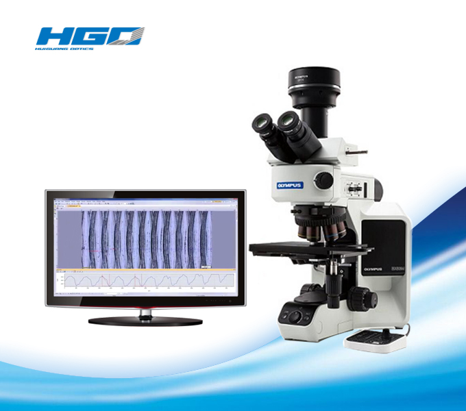
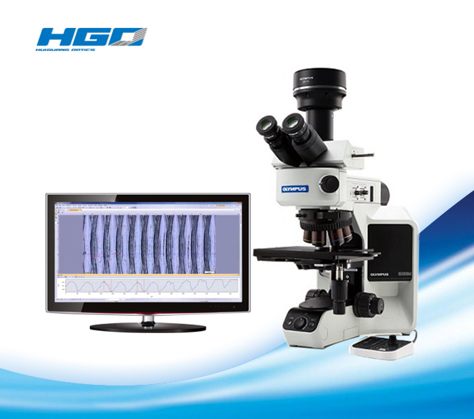
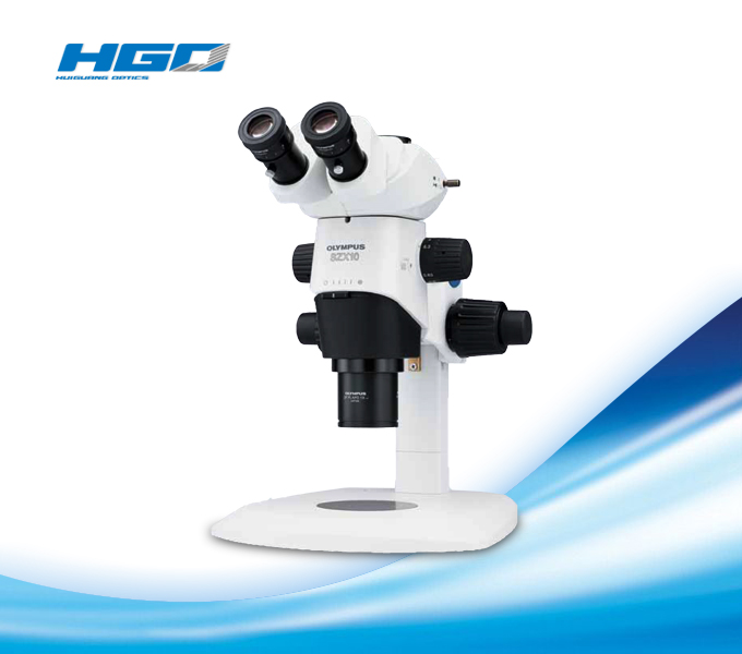
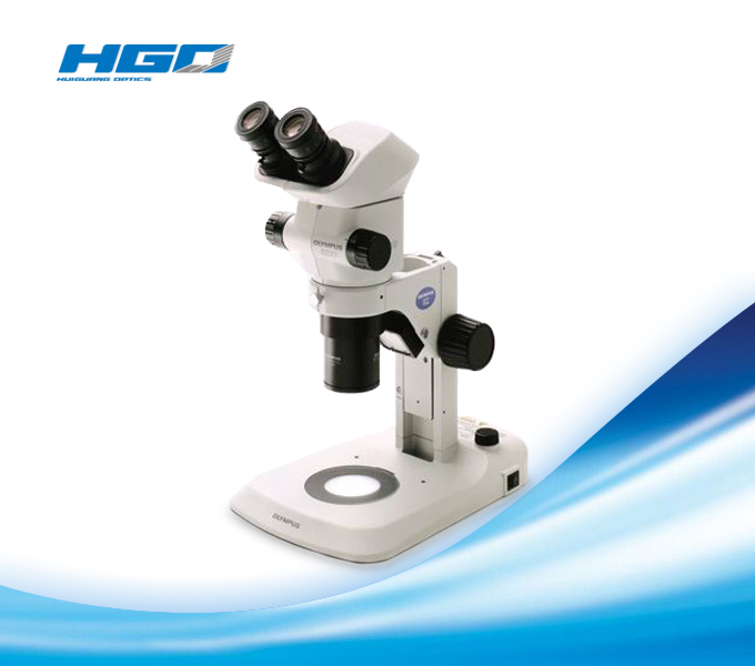
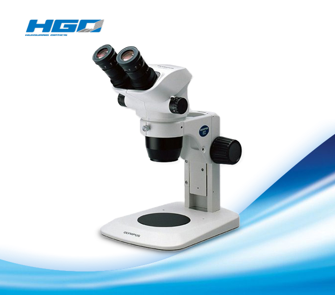
Introduction TO BX53M Metallographic microscope
1、configurations
Modular Design, Build Your System Your Way
● Microscope Frames
There are two microscope frames forreflected light, one also has transmitted Light; capability. An adapter isavailable to raise the illuminator to accommodate taller samples.
Reflected light | Transmitted light | Sample height | ||
1 | BX53MRF-S | ■ | - | 0 to 65 mm |
2 | BX53MTRF-S | ■ | ■ | 0 to 35 mm |
1, 3 | BX53MRF-S + BX3M-ARMAD | ■ | - | 40 to 105 mm |
2, 3 | BX53MTRF-S + BX3M-ARMAD | ■ | ■ | 40 to 75 mm |
Convenient Accessories for Microscopy use
- | HP-2 | Hand press |
- | COVER-018 | Dust cover |

● Stands
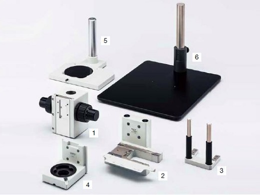
For microscopy applications where thesample will not fit on a stage, the illuminator and optics can be mounted to alarger stand or to another piece of equipment.
BXFM + BX53M Illuminator Configuration
1 | BXFM-F | Frame interface is wall mounting 32 mm pillar |
2 | BX3M-ILH | Illuminator holder |
3 | BXFM-ILHSPU | Counter spring for BXFM |
6 | SZ-STL | Large stand |
BXFM + U-KMAS Illuminator Configuration
1 | BXFM-F | Frame interface is wall mounting 32 mm pillar |
4 | BXFM-ILHS | U-KMAS holder |
5 | U-ST | Stand |
6 | SZ-STL | Large stand |
● Tubes
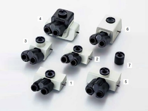
For microscope imaging with eyepieces orfor camera observation, select tubes by imaging type and operator’s postureduring observation.
FN | Type | Angle type | Image | Number of diopter | ||
1 | U-TR30-2 | 22 | Trinocular | Fixing | Reverse | 1 |
2 | U-TR30IR | 22 | Trinocular for IR | Fixing | Reverse | 1 |
3 | U-ETR-4 | 22 | Trinocular | Fixing | Erect | - |
4 | U-TTR-2 | 22 | Trinocular | Tilting | Reverse | - |
5 | U-SWTR-3 | 26.5 | Trinocular | Fixing | Reverse | - |
6 | U-SWETTR-5 | 26.5 | Trinocular | Tilting | Erect | - |
7 | U-TLU | 22 | Single port | - | - | - |
● Illuminators
The illuminator projects light onto thesample based on the observation method selected. Software interfaces with codedilluminators to read the cube position and automatically recognize theobservation method.
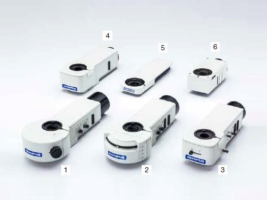
Coded function | Light source | BF | DF | DIC | POL | IR | FL | MIX | AS/FS | ||
1 | BX3M-RLAS-S | Fixed 3 cube position | LED - Built in | ■ | ■ | ■ | ■ | - | - | ■ | ■ |
2 | BX3M-URAS-S | Attachable 4 cube position | LED | ■ | ■ | ■ | ■ | - | - | ■ | ■ |
Halogen | ■ | ■ | ■ | ■ | ■ | - | ■ | ■ | |||
Mercury/Light guide | ■ | ■ | ■ | ■ | - | ■ | ■ | ■ | |||
3 | BX3M-RLA-S | LED | ■ | ■ | ■ | ■ | - | - | ■ | ■ | |
Halogen | ■ | ■ | ■ | ■ | ■ | - | ■ | ■ | |||
4 | BX3M-KMA-S | LED - Built in | ■ | - | ■ | ■ | - | - | ■ | - | |
5 | BX3-ARM | Mechanical arm for transmitted light | |||||||||
6 | U-KMAS | LED | ■ | - | ■ | ■ | - | - | ■ | - | |
Halogen | ■ | - | ■ | ■ | ■ | - | ■ | - | |||
● Light Sources
Light sources and power supplies for sampleillumination, choose the appropriate light source for the observation method.
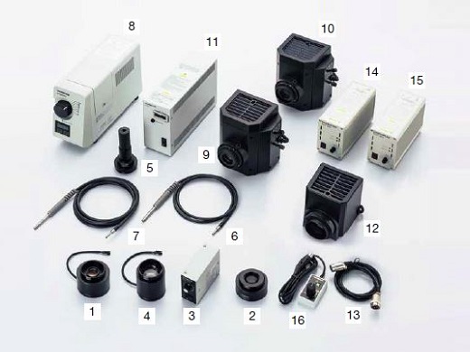
Standard LED Light Resource Configuration
1 | BX3M-LEDR | LED lamp housing for reflected light |
2 | U-RCV | DF converter for BX3M-URAS-S, required for observation with DF and BF when necessary |
3 | BX3M-PSLED | Power supply for LED lamp housing, requires BXFM system |
4 | BX3M-LEDT | LED lamp housing for transmitted light |
Fluorescence Light Resource Configuration
5 | U-LLGAD | Light guide adapter |
2 | U-RCV | DF converter for BX3M-URAS-S, required for observation with DF when necessary |
6, 7 | U-LLG150 | Light guide, length: 1.5 m |
8 | U-HGLGPS | Light source for fluorescence |
9, 10 | U-LH100HG (HGAPO) | Mercury lamp housing for fluorescence |
2 | U-RCV | DF converter for BX3M-URAS-S, required for observation with DF when necessary |
11 | U-RFL-T | Power supply for 100W mercury lamp |
Halogen and Halogen IR Light ResourceConfiguration
12 | U-LH100IR | Halogen lamp housing for IR |
13 | U-RMT | Extender cable for halogen lamp housing, cable length 1.7 m (requires cable extension when necessary) |
14, 15 | TH4-100 (200) | 100V (200V) specification power supply for 100W/50W halogen lamp |
16 | TH4-HS | Hand switch for light intensity of halogen (dimmer TH4-100 (200) without hand switch) |
● Nosepieces
Attachment for objectives and sliders.Select by the number of objectives needed and types; also with/without sliderattachment.
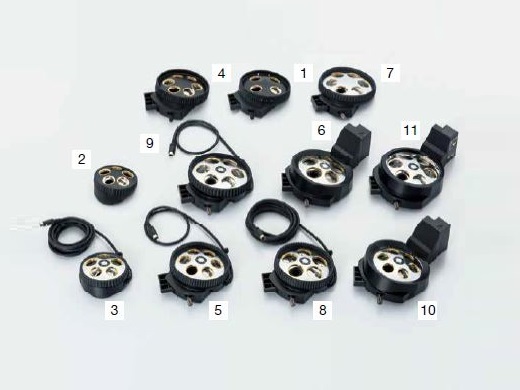
Type | Holes | BF | DF | DIC | MIX | ESD | Number of | ||
1 | U-P4RE | Manual | 4 | ■ | ■ | 4 | |||
2 | U-5RE-2 | Manual | 5 | ■ | |||||
3 | U-5RES-ESD | Coded | 5 | ■ | ■ | ||||
4 | U-D6RE | Manual | 6 | ■ | ■ | ||||
5 | U-D6RES | Coded | 6 | ■ | ■ | ||||
6 | U-D5BDREMC | Motorized | 5 | ■ | ■ | ■ | ■ | ||
7 | U-D6BDRE | Manual | 6 | ■ | ■ | ■ | ■ | ||
8 | U-D5BDRES-ESD | Coded | 5 | ■ | ■ | ■ | ■ | ■ | |
9 | U-D6BDRES-S | Coded | 6 | ■ | ■ | ■ | ■ | ■ | |
10 | U-D6REMC | Motorized | 6 | ■ | ■ | ||||
11 | U-D6BDREMC | Motorized | 6 | ■ | ■ | ■ | ■ |
● Sliders
Select the slider to compliment traditionalbrighfield observation. The DIC slider provides topographic information aboutthe sample with options to maximize contrast or resolution. The MIX sliderprovides illumination flexibility with a segmented LED source in the darkfieldpath.
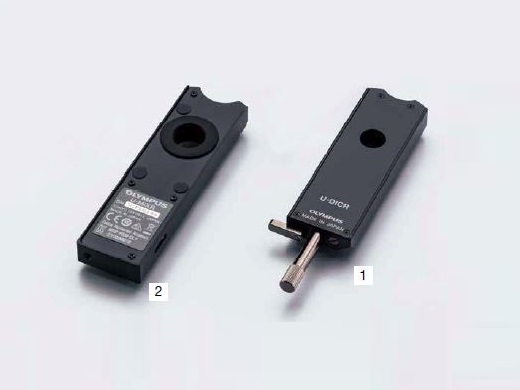
DIC Slider
Type | Amount of shear | Available objectives | ||
1 | U-DICR | Standard | Medium | MPLFLN, MPLAPON, LMPLFLN, and LCPLFLN-LCD |
MIX Slider
Available objectives | ||
2 | U-MIXR | MPLFLN-BD, LMPLFLN-BD, MPLN-BD |
Cable
U-MIXRCBL* | U-MIXR cable, cable length: 0.5 m |
*MIXR only
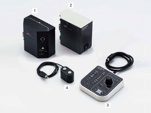
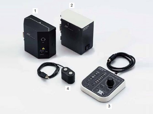
● Controls Box and Hand Switches
Control boxes for interfacing microscopehardware with a PC and hand switches for hardware display and control.
BX3M-CB (CBFM) Configuration
1 | BX3M-CB | Control box for BX53M system |
2 | BX3M-CBFM | Control box for BXFM system |
3 | BX3M-HS | MIX observation control, indicator of coded hardware, programmable function button of software (Stream) |
4 | BX3M-HSRE | Motorized nosepiece rotation |
Cable
- | BX3M-RMCBL (ECBL) | Motorized nosepiece cable, cable length: 0.2 m |
● Stages
Stages and stage plates for sampleplacement. Select based on sample shape and size.
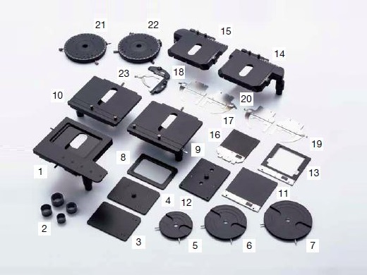
150 mm × 100 mm Stage Configuration
1 | U-SIC64 | 150 mm × 100 mm flat top handle stage |
2 | U-SHG (T) | Silicone rubber operability handle rubber for improvement (thick type) |
3 | U-SP64 | Stage plate for U-SIC64 |
4 | U-WHP64 | Wafer plate for U-SIC64 |
5 | BH2-WHR43 | Wafer holder for 4-3 in. |
6 | BH2-WHR54 | Wafer holder for 5-4 in. |
7 | BH2-WHR65 | Wafer holder for 6-5 in. |
8 | U-SPG64 | Glass plate for U-SIC64 |
76 mm × 52 mm Stage Configuration
14, 15 | U-SVR (L) M | 76 mm × 52 mm right (left) handle stage |
2 | U-SHG (T) | Silicone rubber operability handle rubber for improvement (thick type) |
16 | U-MSSP | Stage plate for U-SVR (/L) M |
17, 18 | U-HR (L) D-4 | Thin slide holder for the right (left) opening |
19, 20 | U-HR (L) DT-4 | Thick slide holder for the right (left) opening, for pressing the slide glass to stage top surface, the specimen is difficult to lift |
100 mm × 100 mm Stage Configuration
9, 10 | U-SIC4R (L) 2 | 105 mm × 100 mm right (left) handle stage |
11 | U-MSSP4 | Stage plate for U-SIC4R (L) 2 |
12 | U-WHP2 | Wafer plate for U-SIC4R (L) 2 |
6 | BH2-WHR43 | Wafer holder for 4-3 in. |
13 | U-MSSPG | Glass plate for U-SIC4R |
Others
21 | U-SRG2 | Rotatable stage |
22 | U-SRP | Rotatable stage for POL, from any position can be 45° click stop |
23 | U-FMP | Mechanical stage for U-SRP/U-SRG2 |
● Camera Adapters
Adapter for camera observation. Selectablefrom required field of view and magnification. Actual observation range can becalculated using this formula: actual field of view (diagonal mm) = viewingfield (viewing number) ÷ objective magnification.
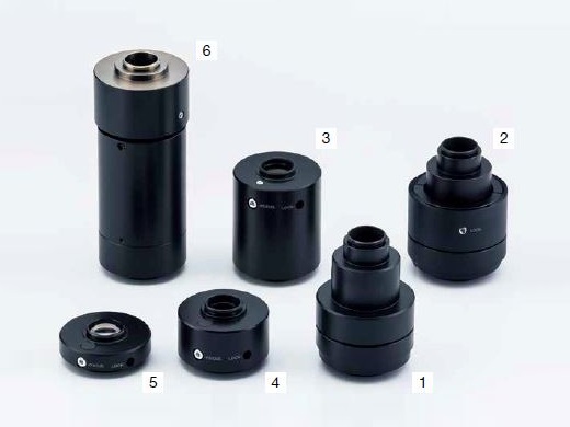
Magnification | Centering adjustment | CCD image area (field number) mm | ||||
2/3 inch | 1/1.8 inch | 1/2 inch | ||||
1 | U-TV1x-2 with U-CMAD3 | 1 | - | 10.7 | 8.8 | 8 |
2 | U-TV1xC | 1 | ø2 mm | 10.7 | 8.8 | 8 |
3 | U-TV0.63xC | 0.63 | - | 17 | 14 | 12.7 |
4 | U-TV0.5xC-3 | 0.5 | - | 21.4 | 17.6 | 16 |
5 | U-TV0.35xC-2 | 0.35 | - | - | - | 22 |
6 | U-TV0.25xC | 0.25 | - | - | - | - |
● Eyepieces
Eyepiece for viewing directly into themicroscope. Select based on desired field of view.

FN (mm) | Diopter adjustment mechanism | Built-in cross reticle | ||
1 | WHN10x | 22 | ||
2 | WHN10x-H | 22 | ■ | |
3 | CROSS WHN10x | 22 | ■ | ■ |
4 | SWH10x-H | 26.5 | ■ | |
5 | CROSS SWH10x | 26.5 | ■ | ■ |
● Optical Filters
Optics filters convert sample exposurelight to various types of illumination. Select the appropriate filter forobservation requirements.
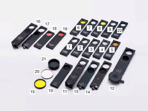
BF, DF, FL
1, 2 | U-25ND25,6 | Neutral density filter, transmittance 25%, 6% |
3 | U-25LBD | Daylight color filter |
4 | U-25LBA | Halogen color filter |
5 | U-25IF550 | Green filter |
6 | U-25L42 | UV-cut filter |
7 | U-25Y48 | Yellow filter |
8 | U-25FR | Frost filter (Required for the BX3M-URAS-S) |
POL,DIC
9 | U-AN-2 | Polarization direction is fixed |
10 | U-AN360-3 | Polarization direction is rotatable |
11 | U-AN360P-2 | High quality polarization direction is rotatable |
12 | U-PO3 | Polarization direction is fixed |
13 | U-POTP3 | Polarization direction is fixed, for use with U-DICRH |
14 | 45-IF546 | Green ø45mm filter for POL |
IR
15 | U-AN360IR | IR polarization direction is rotatable (reduces halation at IR observation when using combination with U-AN360IR and U-POIR) |
16 | U-POIR | IR polarization direction is fixed |
17 | U-BP1100IR | Band pass filter: 1100 nm |
18 | U-BP1200IR | Band pass filter: 1200 nm |
Transmitted Light
19 | 43IF550-W45 | Green ø45 mm filter |
20 | U-POT | Polarizer filter |
Others
22 | U-25 | Empty filter, for use with user's ø25 mm filters |
*AN and PO are not necessary when usingBX3M-RLAS-S and U-FDICR
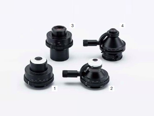
● Condensers
Condensers collect and focus transmittedlight. Use for transmitted light observation.
1 | U-AC2 | Abbe condenser (available from 5x objectives) |
2 | U-SC3 | Swing-out condenser (available from 1.25x objectives) |
3 | U-LWCD | Long working distance condenser for glass plate |
4 | U-POC-2 | Swing-out condenser for POL |
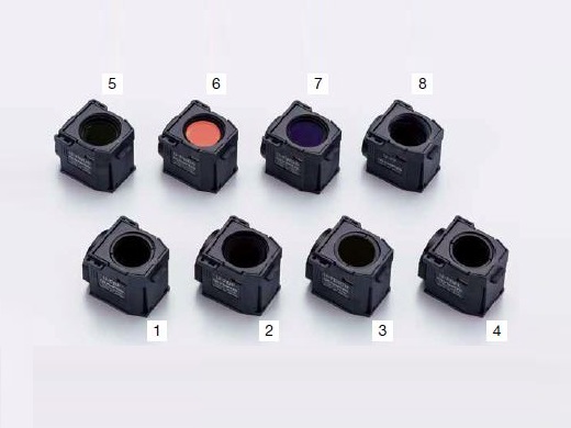
● Mirror Units
Mirror unit for BX3M-URAS-S. Select the unitfor required observation.
1 | U-FBF | For BF, detachable ND filter |
2 | U-FDF | For DF |
3 | U-FDICR | For POL, crossed nicol position is fixed |
4 | U-FBFL | For BF, built-in ND filter (It is necessary to use both BF* and FL) |
5 | U-FWUS | For Ultra Violet-FL: BP330-385 BA420 DM400 |
6 | U-FWBS | For Blue-FL: BP460-490 BA520IF DM500 |
7 | U-FWGS | For Green FL: BP510-550 BA590 DM570 |
8 | U-FF | Empty mirror unit |
*For coaxial episcopic illumination only
● Intermediate Tubes
Various types of accessories for multiplepurposes. For use between tube and illuminator.
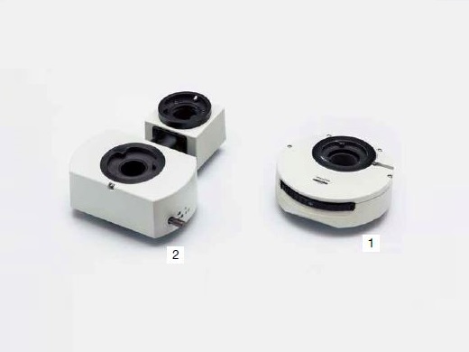
1 | U-CA | Magnification changer (1X, 1.25X, 1.6X, 2X) |
2 | U-TRU | Trinocular intermediate unit |
2、ease of use
● Traditional Techniques Made Easy: SimpleIlluminator
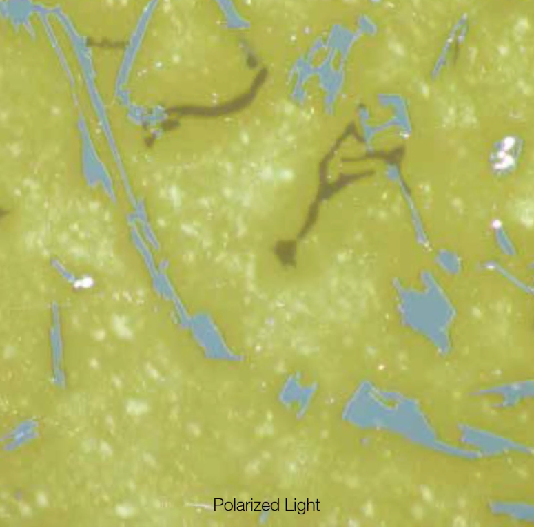
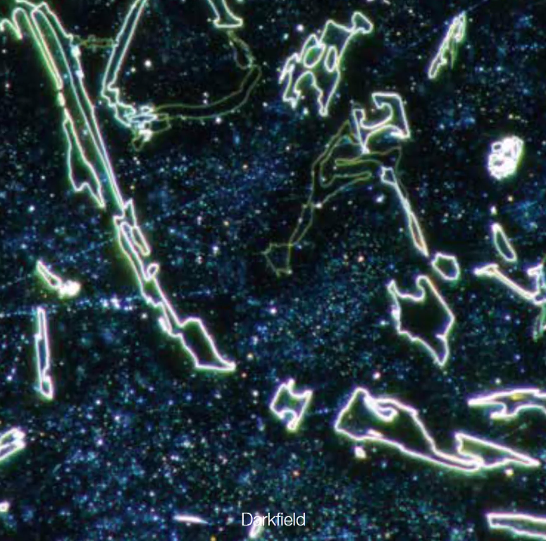
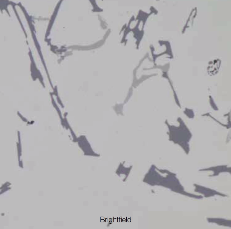
The illuminator minimizes complicatedactions that are usually necessary during microscope operation. A dial at thefront of the illuminator enables the user to easily change the observationmethod. An operator can quickly switch between the most frequently usedobservation methods in reflected light microscopy, such as from brightfield, todarkfield, to polarized light, in order to readily change between differenttypes of analysis. In addition, simple polarized light observation isadjustable by rotating the analyzer.

● Intuitive Microscope Controls: Simple FSand AS Settings
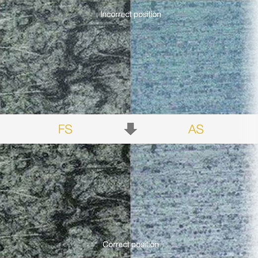
Using the proper aperture stop and fieldstop settings provides good image contrast and makes full use of the numericalaperture of the objective. The legend guides the user to the correct settingbased on the observation method and objective in use.
● Find the Focus Quickly
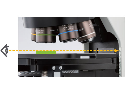
The focus scale index on the frame supportsquick access to the focal point. Operators can roughly adjust the focal pointwithout viewing the sample through an eyepiece, saving time when inspectingsamples that are different heights.
● Easy and Comfortable Operation
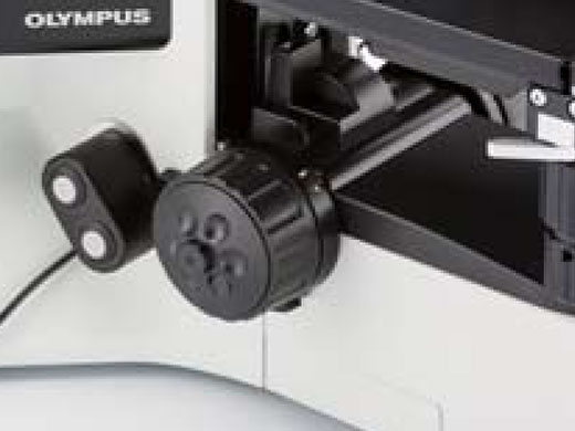
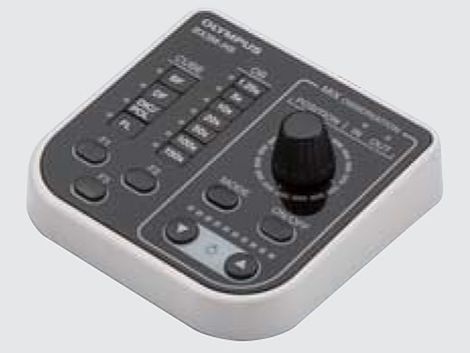
A system design affects users' workefficiency. Both standalone microscope users and those integrating with OLYMPUSStream image analysis software benefit from convenient handset controls thatclearly display the hardware position. The simple handsets enable the user tofocus on their sample and the inspection they need to perform.
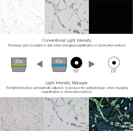
● For Consistent Illumination: LightIntensity Manager
During the initial setup, the illuminationintensity can be adjusted to match the specific hardware configuration of thecoded illuminator and/or coded nosepiece.
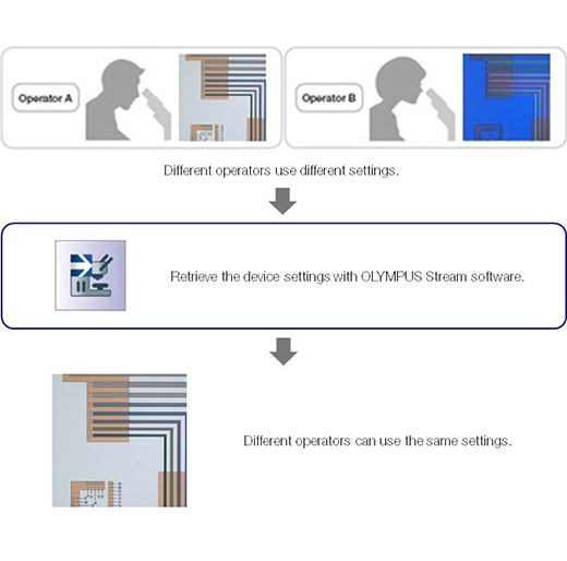
● For Restoring Microscope Settings: CodedHardware
Coded functions integrate the systemsettings of the BX53M with OLYMPUS Stream image analysis software. Theobservation method, illumination intensity, and magnification are automaticallyrecorded by the software and stored with the associated images. Since operatorscan always conduct inspections with the same observation settings, reliableinspection results can be delivered.
3、functionality
● The Invisible Becomes Visible:
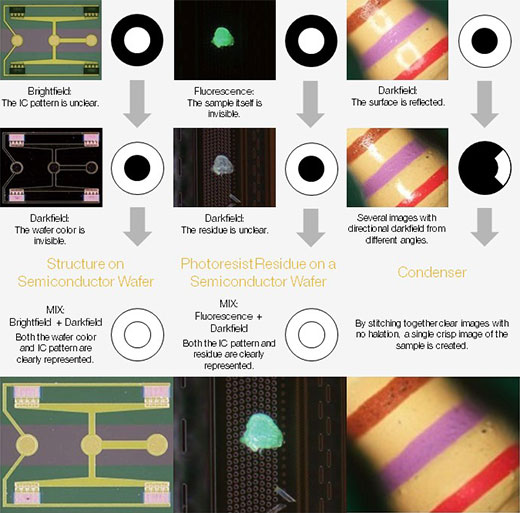
MIX Observation
The BX53M’s MIX observation technologycombines traditional illumination methods with darkfield illumination. When theMIX slider is used, its ring of LEDs shine directional darkfield on the sample.This has a similar effect to traditional darkfield, but provides the ability toselect a quadrant of the LEDs in order to direct the light from differentangles. This combination of directional darkfield and brightfield,fluorescence, or polarization is called MIX illumination, and is especiallyhelpful to highlight defects and differentiate raised surfaces fromdepressions.
● Create All-in-focus Images: EFI
The Extended Focus Imaging (EFI) functionwithin OLYMPUS Stream captures images of samples whose height extends beyondthe depth of focus of the objective and stacks them together to create oneimage that is all in focus. EFI can be executed with either a manual ormotorized Z-axis and creates a height map for easy structure visualization. Itis also possible to construct an EFI image while offline within Stream Desktop.

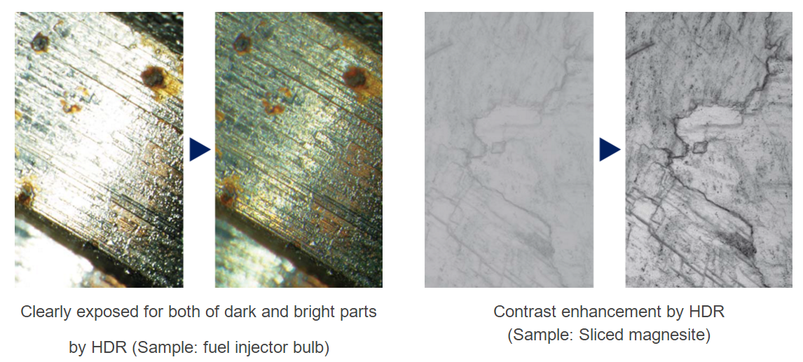
● Capture Both Bright and Dark Areas: HDR
Using advanced image processing, highdynamic range (HDR) adjusts for differences in brightness within an image toreduce glare. HDR improves the visual quality of digital images thereby helpingto generate professional-looking reports.
●Easily Move the Stage for Panorama:Instant MIA
You can now stitch images easily andquickly just by moving the XY knobs on the manual stage; no motorized stage isnecessary. OLYMPUS Stream uses pattern recognition to generate a panoramicimage giving users a wider field of view than a single frame.
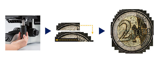
Instant MIA image of a coin
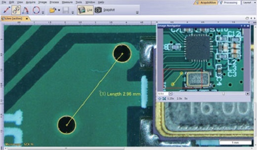
● Routine or Basic Measurement Functions
Various measurement functions are availablethrough OLYMPUS Stream so that the user can easily obtain useful data from theimages. For quality control and inspection, measuring features on images areoften required. All levels of OLYMPUS Stream licenses include interactivemeasurement functions such as distances, angles, rectangles, circles, ellipses,and polygons. All measured results are saved with the image files for furtherdocumentation.
● Materials Science Solutions
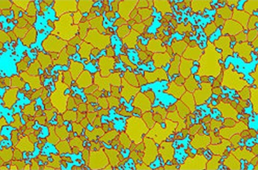
OLYMPUS Stream offers an intuitive,workflow-oriented interface for complex image analysis. At the click of abutton, the most complex image analysis tasks can be executed quickly,precisely, and in compliance with most common industrial standards. With asignificant reduction in processing time for repeated tasks, materialsscientists can concentrate on analysis and research. Modular add-ins forinclusions and intercept charts are easily performed at any time.
● 3D Sample Measurement
When using an external motorized focusdrive, an EFI image can be quickly captured and displayed in 3D. The heightdata acquired can be used for 3D measurements on the profile or from the singleview image.
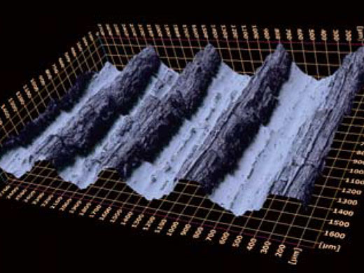

3D surface view (Roughness test sample) Single view and 3D profile measurement
4、image quality
● Superior Optical Performance: Wave Front Aberration Control
The optical performance of objective lensesdirectly impacts the quality of the observation images and analysis results.Olympus UIS2 high-magnification objectives are designed to minimize wavefrontaberrations, delivering reliable optical performance.
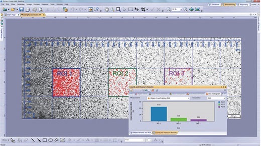
● Count and Measure
Object detection and size distributionmeasurement are among the most important applications in digital imaging.OLYMPUS Stream incorporates a detection engine that utilizes threshold methodsto reliably separate objects (e.g., particles, scratches) from the background.

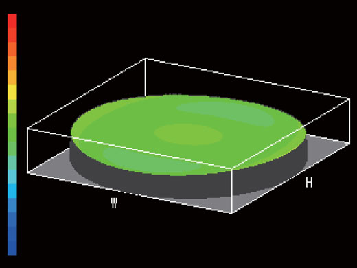
Bad wavefront Good wavefront (UIS2 objective)
● Consistent Color Temperature: High-Intensity White LED Illumination
The BX53M utilizes a high-intensity whiteLED light sources for both reflected and transmitted light. The LED maintains aconsistent color temperature regardless of intensity. LEDs provide efficient,long-life illumination that is ideal for inspecting materials scienceapplications.

Halogen: Color varies with light intensity.

LED: Color is consistent with lightintensity and clearer than halogen.
* All images captured using auto exposure
● Support Precise Measurement: Auto Calibration
Similar to digital microscopes, automaticcalibration is available when using OLYMPUS Stream. Auto-calibration eliminateshuman variability in the calibration process leading to more reliablemeasurements. Auto calibration uses an algorithm that automatically calculatesthe correct calibration from an average of multiple measurement points. Thisminimizes variance introduced by different operators and maintains consistentaccuracy, improving reliability for regular verification.

● Seamless Stitching: Image Shading Correction
OLYMPUS Stream software features shadingcorrection to accommodate for shading around the corners of an image. When usedwith intensity threshold settings, shading correction provides a more preciseanalysis.

● Semiconductor wafer (Binarized image):Shading correction produces even illumination across the field of view.
Technical Specifications
Entry | Standard | Advanced | ||||||
Optical system | UIS2 optical system (infinity-corrected) | |||||||
Main unit | Microscope frame | BX53MRF-S | BX53MTRF-S | BX53MRF-S | BX53MTRF-S | BX53MRF-S | BX53MTRF-S | |
Focus | Stroke: 25 mm | |||||||
Max. specimen height | Reflected: 65 mm (w/o spacer), 105 mm (with BX3M-ARMAD) | |||||||
Observation tube | Wide field (F.N.22) | U-TR30-2-2 | ||||||
Illumination | Reflected light | BX3M-KMA-S | BX3M-RLAS-S | |||||
- | BX3M-LEDT | - | BX3M-LEDT | - | BX3M-LEDT | |||
Revolving nosepiece | U-5RE-2 | U-D6BDRE | U-D6BDRES-S | |||||
Eyepiece(F.N.22) | WHN10 | |||||||
MIX observation | - | BX3M-CB | ||||||
Condenser (Long working distance) | - | U-LWCD | - | U-LWCD | - | U-LWCD | ||
Power cable | UYCP (x1) | UYCP (x2) | ||||||
Weight | Reflected: approx.15.8 kg (microscope frame 7.4 kg) | |||||||
Objectives | MPLFLN set | MPLFLN5X, 10X, 20X, 50X, 100X | - | |||||
MPLFLN BD set | - | MPLFLN5XBD, 10XBD, BD, 50XBD, 100XBD | ||||||
MPLFLN-BD, LMPLFLN-BD set | - | MPLFLN5XBD, 10XBD, LMPLFLN20XBD, 50XBD, 100XBD | ||||||
Stage (X x Y) | 76 mm x 52 mm set | U-SVRM, U-MSSP | ||||||
100 mm x 10 0mm set | U-SIC4R2, U-MSSP4 | |||||||
100 mm x 100 (G) mm set | U-SIC4R2, U-MSSPG | |||||||
150 mm x 100 mm set | U-SIC64, U-SHG, U-SP64 | |||||||
150 mm x 100 (G) mm set | U-SIC64, U-SHG, U-SPG64 | |||||||
Option | MIX observation set* | BX3M-CB, BX3M-HS, U-MIXR, U-MIXRCBL | - | |||||
DIC* | U-DICR | |||||||
Intermediate Tubes | U-CA, U-EPA2, U-TRU-1-2, U-TRU | |||||||
Filters | U-25ND6, U-25ND25, U-25LBD, U-25LBA, U-25Y48, U-AN360-3, U-AN360P, U-PO3, U-POTP3, U-25IF550, U-25L42, U-25, U-25FR | |||||||
Filter for condenser | 43IF550-W45, U-POT | |||||||
Stage plate | U-D6BDRES-S, U-D6RE-ESD-2, U-D6BDRES-ESD, U-5RES-ESD | |||||||
Specimen holder | U-HRD-4, U-HLD-4, U-HRDT-4, U-HLDT-4 | |||||||
Handle rubber | U-SHG, U-SHGT | |||||||
*Cannot be used with U-5RE-2.
BX53M / BXFM ESD UNITS
Items | Microscope frame | BX53MRF-S, BX53MTRF-S |
Illuminator | BX3M-KMA-S, BX3M-RLA-S, BX3M-URAS-S, BX3M-RLAS-S | |
Nosepiece | U-D6BDRES-S, U-D6RE-ESD, U-D5BDREMC-ESD, U-5RES-ESD | |
Stage | U-SIC4R2, U-SIC4L2, U-MSSP4 |
SPECIFICATIONS OF BX53M SUGGESTEDCONFIGURATION FOR DEDICATED USE
Fluorescence | Infrared | Polarized | |||||
Optical system | UIS2 optical system (infinity-corrected) | ||||||
Main unit | Microscope frame | BX53MRF-S | BX53MTRF-S | BX53MRF-S | BX53MTRF-S | ||
Focus | Stroke: 25 mm | ||||||
Max. specimen height | Reflected: 65 mm (w/o spacer), 105 mm (with BX3M-ARMAD) | ||||||
Observation tube | Wide field (F.N.22) | U-TR30-2 | U-TR30IR | U-TR30-2 | |||
Polarized Light Intermediate Attachment (U-CPA) | Bertrand Lens | - | - | Focusable | |||
Bertrand Field Stop | - | - | ø3.4 mm diameter (fixed) | ||||
Engage or disengage Bertrand lens changeover between orthoscopic and conoscopic observation | - | - | Position of slider ● in | ||||
Analyzer Slot | - | - | Rotatable Analyzer with Slot (U-AN360P-2) | ||||
Illumination | Reflected light | FL observation | BX3M-URAS-S | - | - | ||
IR observation | - | BX3M-RLA-S | - | ||||
Transmitted light | POL observation | - | - | BX3M-LEDT | |||
Revolving nosepiece | U-D6BDRES-S | U-5RE-2 | U-P4RE | ||||
Eyepiece(F.N.22) | WHN10X | ||||||
WHN10X-H | CROSS-WHN10X | ||||||
Mirror units | U-FDF | - | |||||
Filter / Polarizer / Analyzer | U-25FR | U-BP1100IR/U-BP1200IR | 43IF550-W45 | ||||
U-POIR | U-AN360IR | U-AN360P-2 | |||||
Condenser | U-LWCD | - | U-POC-2 | ||||
Slider / Compensators | - | U-TAD | |||||
U-TP530 / U-TP137 | |||||||
Power cable | UYCP (x1) | UYCP (x2) | UYCP (x1) | ||||
Weight | Reflected: approx.15.8 kg (microscope frame 7.4 kg) | Reflected/transmitted: approx. 18.3 kg (microscope frame 7.6 kg) | Approx.18.9 kg (microscope frame 7.4 kg) | Approx.16.2 kg (microscope frame 7.6 kg) | |||
Reflected FL light source | Light guide | U-HGLGPS, U-LLGAD, U-LLG150, SHI-130OL Light guide set | - | - | |||
Mercury lamp | U-LH100HGAPO1-7, USH-103OL (x2), U-RFL-T, U-RCV Mercury lamp set | - | - | ||||
Objectives | MPLFLN set | MPLFLN5X, 10X, 20X, 50X, 100X | - | - | |||
MPLFLN BD set | MPLFLN5XBD, 10XBD, BD, 50XBD, 100XBD | - | - | ||||
MPLFLN-BD, LMPLFLN-BD set | MPLFLN5XBD, 10XBD, LMPLFLN20XBD, 50XBD, 100XBD | - | - | ||||
IR set | - | LMPLN5XIR,10XIR,LCPLN20XIR,50XIR,100XIR | - | ||||
POL set | - | - | UPLFLN4XP,10XP,20XP,40XP | ||||
Stage (X x Y) | 76 mm x 52 mm set | U-SVRM, U-MSSP | |||||
100 mm x 10 0mm set | U-SIC4R2, U-MSSP4 | ||||||
100 mm x 100 (G) mm set | U-SIC4R2, U-MSSPG | ||||||
150 mm x 100 mm set | U-SIC64, U-SHG, U-SP64 | ||||||
150 mm x 100 (G) mm set | U-SIC64, U-SHG, U-SPG64 | ||||||
POL set | - | I-SRP-1-2+U-FMP | |||||
Option | MIX observation set* | BX3M-CB, BX3M-HS, U-MIXR, U-MIXRCBL | |||||
DIC* | U-DICR | ||||||
Intermediate Tubes | U-CA, U-EPA2, U-TRU-1-2, U-TRU | ||||||
Filters | U-25ND6, U-25ND25, U-25LBD, U-25LBA, U-25Y48, U-AN360-3, U-AN360P, U-PO3, U-POTP3, U-25IF550, U-25L42, U-25, U-25FR | ||||||
Filter for condenser | 43IF550-W45, U-POT | ||||||
Stage plate | U-WHP64, BH2-WHR43, BH2-WHR54, BH2-WHR65, U-WHP2, BH2-WHR43 | ||||||
Specimen holder | U-HRD-4, U-HLD-4, U-HRDT-4, U-HLDT-4 | ||||||
Handle rubber | U-SHG, U-SHGT | ||||||
*Cannot be used with U-5RE-2
